Effects of ID Oxide on Embrittlement After LOCA Scenario
Harold Scott and Ralph Meyer
U.S. Nuclear Regulatory Commission
+1 301 415 6771, fax 5160, hhs@nrc.gov
Abstract
The NRC's cladding performance program at Argonne National Laboratory (ANL) is testing high-burnup cladding segments subjected to LOCA temperature transients. Tests have been conducted with segments from Limerick (9×9 Zircaloy-2) and H.B. Robinson (15×15 Zircaloy-4) reactors. Companion tests are conducted with unirradiated cladding to generate baseline data for comparison with the high-burnup fuel results.
Recent presentations by Ralph Meyer of NRC (RIC, March 2006, ANS-Reno, June 2006, and TopFuel, Spain, October 2006) have described embrittlement mechanisms that cause loss of ductility. The retention of post-quench ductility is the basis for NRC’s licensing criteria. This paper discusses mechanism Number 6, “Oxygen Pickup from the Cladding Inside Diameter.”
It would be desirable to examine those Halden IFA-650 tests that experience cladding temperatures >1000º C for evidence of ID oxygen diffusion. Metallography at ID locations far from the balloon could be examined in order to measure the depth of the alpha layer.
1. Introduction
During a loss-of-coolant accident (LOCA), the cladding temperature will rise and several phenomena will occur as illustrated in Fig. 1.
Fig. 1. Schematic cladding temperature during LOCA
At about the temperature that rupture occurs, the cladding metal will change from the alpha phase (HCP) to the beta phase (BCC). Above that temperature, oxidation on the surface of the metal and diffusion of oxygen into the metal become rapid. Increased concentrations of oxygen in the metal lead to loss of ductility or embrittlement.
Recent presentations by Ralph Meyer of NRC (RIC, March 2006 [1], ANS-Reno, June 2006 [2], and TopFuel-Spain, October 2006 [3]) have described embrittlement mechanisms that cause loss of ductility. They are :
· Beta-layer Embrittlement by Oxygen
· Beta-layer Thinning
· Localized Hydrogen-induced Embrittlement in the Balloon
· Hydrogen-enhanced Beta-layer Embrittlement by Oxygen
· Hydrogen-induced Embrittlement from Breakaway Oxidation
· Oxygen Pickup from the Cladding Inner Surface at Locations away from the Balloon
2. Oxygen Distribution
After going through a temperature transient such as illustrated in Fig. 1, the oxygen distribution in the cladding will be as shown in Fig. 2.
Fig. 2. Oxygen concentration in Zircaloy after oxidation in steam and cooling to room temperature.
Oxygen has diffused into the beta phase metal, and after a short time at high temperature the concentration in the beta phase has exceeded its solubility limit. The portion of the beta phase that is above this limit converts back to the alpha phase, which can hold more oxygen. At room temperature, the beta layer converts back to the alpha phase, but both the prior beta layer and the oxygen stabilized alpha layer are readily visible under the microscope as seen in Fig. 3.
Fig. 3. Unirradiated Zircaloy cladding after oxidation in steam at 1200̊ C for 600 seconds.
Notice from Fig. 2, that the oxygen concentration at the boundaries of the alpha layer are well defined at about 7% on the outside and 0.6% on the inside, depending somewhat on temperature.
3. Early Observations of ID Oxygen Pickup
In 1977, Hobbins and coworkers conducted power-cooling mismatch (PCM) tests in the Power Burst Facility in Idaho. [4] They observed an inside diameter (ID) oxide layer everywhere except in the neighborhood of a pellet chip, where the pellet and cladding were not in hard contact, as shown in Fig. 4.
Fig. 4. Cladding collapse into void in PBF test, showing presence of alpha-Zircaloy except in cladding adjacent to void. Cladding temperature about 1025̊ C. OD is at top of figure.
Hobbins observed that the thickness of the ID alpha layer was of comparable magnitude as the outside diameter (OD) alpha layer, which developed as a result of the reaction with steam in the test. Hobbins noted that oxygen diffusion into the Zircaloy was producing embrittlement, and that only where good contact between fuel and cladding was maintained was the reaction observed on the inside. Using embrittlement criteria, Hobbins concluded that a “two-sided reaction model is appropriate for these PCM tests in which almost as much oxygen is entering the cladding on the inside surface from the Zircaloy-UO2 reaction as is coming from the outside surface and the Zircaloy-H2O reaction.”
Two years later, Hofmann and Politis performed laboratory experiments at Karlsruhe to confirm Hobbins observations. [5] They put fresh UO2 pellets inside sealed unirradiated Zircaloy tubes and heated them in argon under various pressures. These investigators found a reaction between the Zircaloy cladding and the UO2 fuel pellet when there was sufficient pressure to cause solid contact, and they noted that oxygen from the UO2 also diffuses into the Zircaloy to form the alpha phase as shown in Fig. 5.
Fig. 5. UO2 -Zircaloy interaction after 30 minutes at 1200̊ C under an argon pressure of 10 bars.
Hofmann and Politis compared their observed alpha layer with that in steam oxidation experiments performed in the same laboratory by Leistikow and Schanz and concluded “that the thickness of reaction zones formed in the Zircaloy- UO2 reaction experiments and the Zircaloy/steam oxidation experiments is nearly identical.”
4. Recent Observations of ID Oxygen Pickup
Although most of the samples used in the Argonne program have been oxidized on two sides, a short series of 1-sided tests were run with irradiated rods from the H. B. Robinson PWR having a burnup of about 65 GWd/t. These defueled specimens were oxidized at 1200̊ C with steam flowing over the outside and argon flowing through the inside of the tube segment. Microscopy was done on two of these specimens, and both show a substantial ID alpha layer. One sample has a measured ID alpha layer of 36±5 microns compared with an OD alpha layer of 42±4 microns, and this specimen is shown in Fig. 6.
Fig. 6. Inner surface of 64 GWd/t H. B. Robinson PWR cladding after 1-sided oxidation at 1200̊ C, showing well developed alpha layer.
The other specimen had a measured ID alpha layer of 35±8 microns compared with an OD alpha layer of 58±7 microns. It is presumed that this oxygen came from the ZrO2 bonding layer on the ID of the cladding. It can be noted that these specimens had been etched to remove all traces of UO2 , which was attached to the other side of the bonding layer. Thus the somewhat smaller thickness of the ID alpha layer compared with the OD layer is probably the result of removing much of the ID oxygen source, leaving a limited amount in the bonding layer that was totally consumed.
A number of 1-sided tests were also run with irradiated rods from the Limerick BWR having a burnup of about 55 GWd/t. These specimens had also been etched to remove all traces of UO2, which was attached to the other side of the bonding layer. The specimens had a bonding layer that was not uniform around the cladding ID and no ID alpha layer was seen after holding at 1200̊ C for about 300 seconds. However, calculations show that oxygen from an alpha layer would have continued to diffuse into the beta layer until its oxygen content were too low to stabilize the alpha phase.
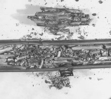
Four integral tests were run with the irradiated Limerick rods, and three of them were run at high temperature in steam (300 seconds at 1200̊ C). Steam was present on the ID only in the balloon region. Away from the balloon, only one local region in one of the tests (ICL#2) exhibited an ID alpha layer as shown in Fig. 7. Although not conclusive, these results are consistent with (a) incomplete bonding in BWR fuel at ~55 GWd/t, (b) formation of an alpha layer only in the bonded regions, and (c) diffusion of oxygen from the bond layer resulting in both reduction of the bond layer and disappearance of the alpha layer.
Fig. 7. Evidence of an ID alpha layer at location B and absence of such a layer at location A in a fuel rod specimen (including fuel) that was held at 1200̊ C for 300 seconds in an integral LOCA test.
Bonding occurs earlier in PWR fuel than in BWR fuel because the higher system pressure in PWRs results in more cladding creepdown. Bonding between the fuel and the cladding eventually occurs in BWRs as well. From ANL characterization work performed for Limerick BWR high-burnup (55-57 GWd/MTU) fuel, Surry low-burnup (36 GWd/MTU) fuel, TMI-1 PWR intermediate-burnup (48 GWd/MTU), and H. B. Robinson PWR high-burnup (63-67 GWd/MTU) fuel, it appears that bonding (and hence ID oxygen ingress during a LOCA) would begin at ≈30 GWd/t in PWR fuel and be complete around ≈50 GWd/t, whereas it would not begin in BWRs until ≈40-50 GWd/t.
5. Conclusion and Recommendation
It is clear that if oxygen sources are present on the OD and the ID of the cladding, oxygen will diffuse into the metal equally from both sides as in a multi-layer diffusion “couple” such as illustrated in Fig. 8.
Fig. 8. multi-layer diffusion “couple”
It is also clear that bonding between the UO2 fuel and the zirconium-alloy cladding can provide the good contact that is needed. What is not clear are the conditions under which this bonding is sufficiently complete to promote ID oxygen diffusion.
It would be very valuable if microscopy could be done on IFA-650 specimens at locations away from the balloon to compare the OD alpha layer with any ID alpha layer that might be present.
6. References
[1] R. O. Meyer, http://www.nrc.gov/public-involve/conference-symposia/ric/past/2006/ slides/t1bc-meyer.pdf
[2] Ralph O. Meyer (NRC), Michael C. Billone (ANL), Technical Basis for Revision of LOCA Embrittlement Criteria, 2006 ANS Annual Meeting June 6, 2006, Reno, Nevada, USA http://www.ans.org/meetings/docs/2006/am2006-official.pdf
[3] R. O. Meyer, http://www.euronuclear.org/events/topfuel/transactions/Topfuel-Technical-Session.pdf
[4] R. R. Hobbins, G. R. Smolik, and G. W. Gibson, “Zircaloy Cladding Behavior During Irradiation Tests Under Power-Cooling-Mismatch Conditions,” Zirconium in the Nuclear Industry, ASTM STP 633, 1977, pp. 182-208.
[5] P. Hofmann and C. Politis, “Chemical Interaction Between Uranium Oxide and
Zircaloy-4 in the Temperature Range Between 900 and 1500̊ C,” Zirconium in the Nuclear Industry, ASTM STP 681, 1979, pp. 537-560. see also Journal of Nuclear Materials, Volume 189, July 1992, Pages 46-64.
Click on the following figure 5 to enlarge. Then use you back arrow to return.

No comments:
Post a Comment